sky59
-
Постов
11 -
Зарегистрирован
-
Посещение
Информация о sky59

- День рождения 12.08.1959
Достижения sky59
")
Newbie (1/14)
0
Репутация
-
When you turn on the key automatically SRS selftest is started. This checks if all airbags have 2Ohm resistance. Of course it does not connect 12V to the bags during tests!!!! It would explode all of them! Instead with small current it check all circuits. Small enough to be sure not to explode airbags! Do not worry for 12V/2R=6A, if this happens you probably had an accident and then it doesnot matted if any resistor burned..... :-)
-
Works, thanx see attached video ABG___focusOK.rar
-
Finally I used Beeprog programmer from www.elnec.sk Freescale programmer failed..... :-) I attach eeprom, could someone helo to clean it from crash? thank you spasiba /I used to learn russian langauge for 10 yers but I can not write azbuka over here/ crashed.rar
-
in a meantime I studied some application notes and realized that there IS possibility to read eeprom if processor is protected there are some hardware BDM commands and through these some registers can be written, BDM on chip memory enabled and BDM started..... then we can do what we want are you sure UPA-USB is doing this to overcome stupid motorola protection? or do you know such programmer? because it seems my processor is protected..... see AN and look for hardware commands... :-) AN2104.pdf
-
I do not remember the name but it is professional that we use in company, so it does only what is allowed by motorola is it normally BDM mode disabled? it is standard 2M5T-14B056-DD
-
I can not read EEPROM with professional programmer! Is microcontroler secured ? What programmer must I use?
-
in a meantime a managed to connect with thin wires to the "connector", I did not add solder I only heat-up from one side PCB and from front I put wires in the vias... tomorrow I take it to work on profi programmer.... can anybody confirm what addresses I should fill up with FF?

-
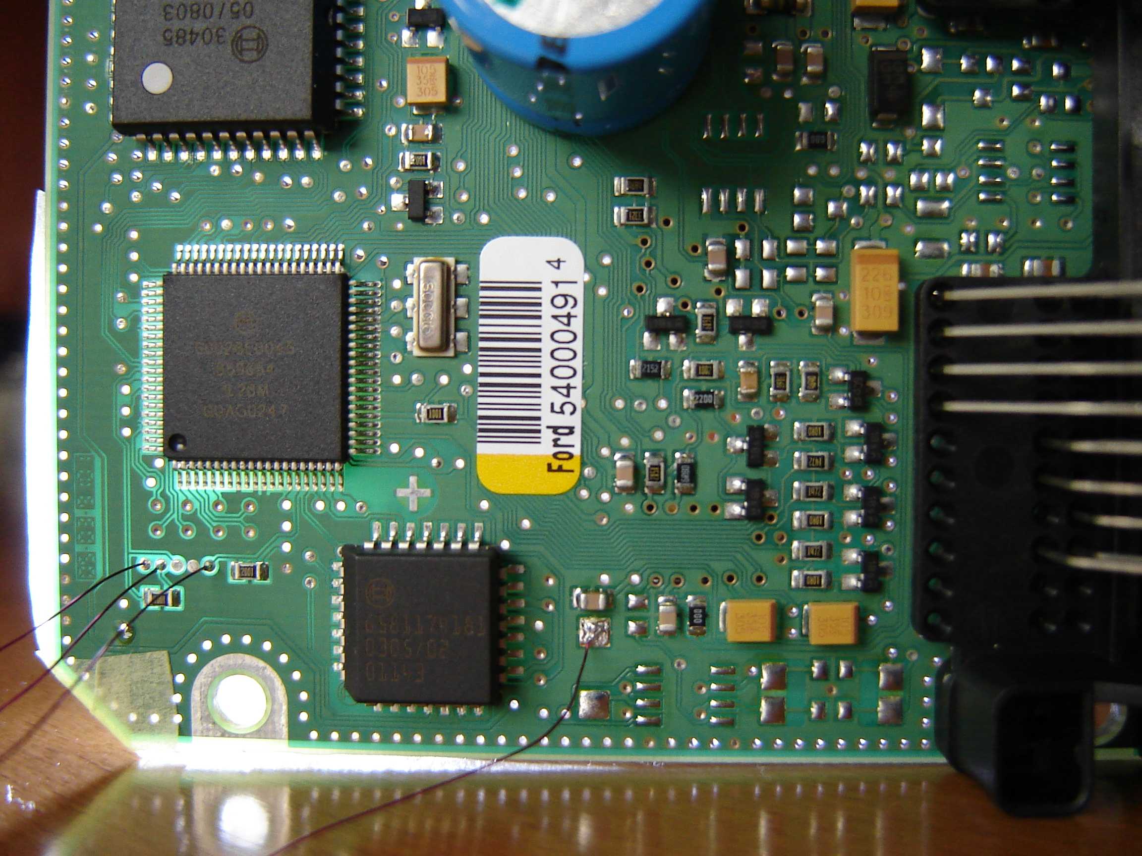
Thank you, but I am not able to connect directly on microprocessor pins...... Am I too old? :-) for this I took macrophoto of PCB to find connector where also manufacturer connects an dit seems I have found it. Tomorrow I am going to read EEPROM with programmer so I will test it but I wanted to be sure.......
-
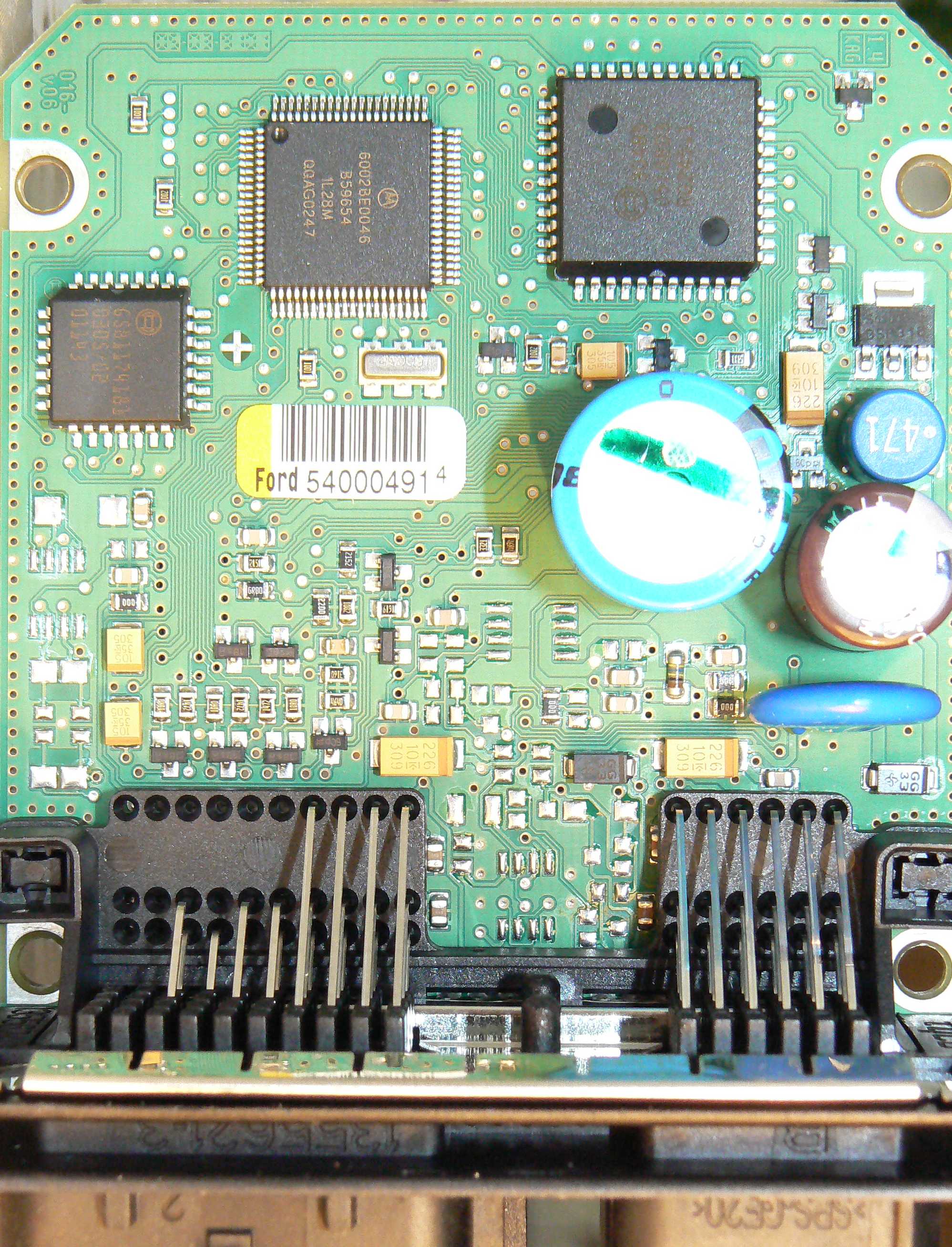
Hi friends, I could not find any picture of PCB of any airbag computer. So I attach one. I am going to repair it because it exploded already airbag /seat close to driver/ Another picture shows places where programmer can be connected. I found these by watching PCB routes and measuring resistances. It seems that +5V for programmer has got 1Ohm resistance in series so it can only be used to inform programmer about +5V ? Can anybody please confirm that connector is correctly identified? /BKGD, GND, VFP, +5, RESET/ Please, if anybody knows what should I delete in EEPROM can write it over here? I mean space in EEPROM from 0x??? to 0x??? must be filled with FF. Thank you for the help! I hope my photos will be usefull!
-
Hello all,
I am Slovak and fortunately I can read Russian language and understand it ! There are a lot excellent internet sites on Russia!
-
what form? my profile? thankx!